> Details
> Details
Number of vertices and components
The structure of polyface meshes is subject to certain limitations. Both the number of components and the number of vertices must not exceed 32767.
Mostly a mesh will have more vertices than components. At worst - if it consists of isolated quadrangles only - there will be four times as many vertices as components. Therefore it may be critical if the number of designated mesh components is greater than a fourth of the maximum, i. e. greater than 8191.
The SEW function tests all corners or end points of the components whether they are identical to other vertices because no vertex should be unnecessarily stored twice. This search is the most time-consuming part of the SEW function.
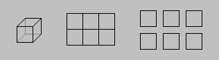
The drawing shows three arrangements of six faces:
with 8 vertices, with 12 vertices, with 24 vertices.
The "revsurf", "rulesurf", "ai_sphere", ... commands create polygon meshes. Their structure differs slightly from polyface mesh structure.
Polygon meshes always consist of 3D faces arranged in a quasi-rectangular scheme of rows and columns and connected by their edges. There can be at most 32767 rows, and 32767 columns as well. Altogether a polygon mesh may have considerably more component faces than a polyface mesh can have.
On the other hand, polyface meshes allow random arrangement of their components. A polyface mesh can have "holes" in it, or it can even be totally unconnected - despite of this, AutoCAD / IntelliCAD considers the mesh as a single object until it has not been dismantled by the "explode" command.
Types of components
Another advantage of polyface meshes: Not only 3D faces can be included in a polyface mesh but also lines and points. By doing this you may construct branching polylines.
Unfortunately, mehes do not allow linetype assignments. Points are always displayed in 0 mode when included in a mesh (i. e. without crosshairs). The current value of the "pdmode" system variable has no influence on that.
Invisible edges
The edges of faces, the lines, and the points in a polyface mesh can be invisible (independent of other objects hiding them). This is of special interest when you want to create a single polygonal face with more than four corners by means of combining a set of quadrangles or triangles. AutoCAD offers the "edge" command for such purposes. But you may also use "3dface" or "pface" or the AutoCAD 14 "ddmodify" command or the AutoCAD 2000 "properties" command. The edges concerned should be made invisible before applying the SEW function.
Invisible edges of this type are shown on the screen by setting the "splframe" system variable to 1 followed by regenerating the drawing.
Multicolored meshes
The "pface" command (being not very convenient) enables the faces of a mesh to be assigned to different colors and even to different layers. (Besides, AutoCAD 2000 allows multicolored 3D solids.) But this may easily cause confusion and mistakes; therefore it should be handled with care.
Surface fit meshes
When applying the SEW function to a surface fit polygon mesh it should be noted that the conversion into a polyface mesh precludes refining by setting U and V values afterwards. (The XSLICE function implies a similar restriction. See also the AutoCAD 14 "ddmodify" command, the AutoCAD 2000 "properties" command, the AutoCAD "splframe", "surfu", and "surfv" system variables.)
IntelliCAD does not display surface fit meshes correctly.
Shading
The Gouraud shading mode of AutoCAD 2000 gives a very smooth appearance to polygon meshes. Polyface meshes with smooth edges are obtained by rendering only.
> Details
> Details